
In part one of this series we explored how to generate resources for the SSD1322 OLED driver chip from Solomon Systech. In this post we’ll dive deeper into the inner workings of the SSD1322 OLED driver chip. We’ll also utilize the resources we generated in the previous post in a simple example. We’ll use a display manufactured by NewHaven Display to test our code. However our code should work for other displays based on the SSD1322. Let’s dive in!
Inside The SSD1322 Driver Chip
The SSD1322 driver chip controls the OLED pixels using segment and common drivers which are basically transistors switches.
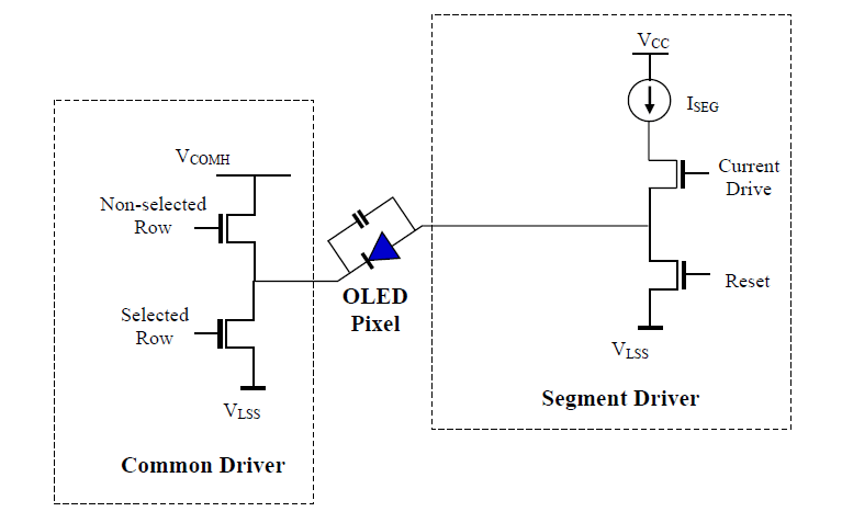
OLED segment and common drivers
All OLED pixels on the same row share a common cathode and all the OLED pixels on the same column share a segment driver. Hence the OLED driver scans the commons sequentially, row by row while manipulating (turning on and off) the segment drivers to show the appropriate image for the row. By scanning the rows at a fast pace our eyes are fooled into believing a static image resides on the screen.
Each oled pixel is modelled as an LED in parallel with a parasitic capacitance, requiring four phases/steps to turn on. First the previous data is cleared, this is because the parasitic capacitance could still hold a charge (data) from being previously turned on. The length of time required for this phase depends on the size of the parasitic capacitance. Next the pixel is pre-charged to a certain voltage level, Vp. In phase 3 the pixel is driven to the final driving voltage via a second pre-charge. Finally a constant current is applied to the pixel.
After going through this cycle, the chip goes back to phase 1 and repeats the cycle for the next row of image data, hence running continuously to refresh data on the screen. We can better visualize this process from the image below which is taken from the datasheet. In summary the segment voltage turns the pixel on or off while the common voltage selects the row to display the segment data.
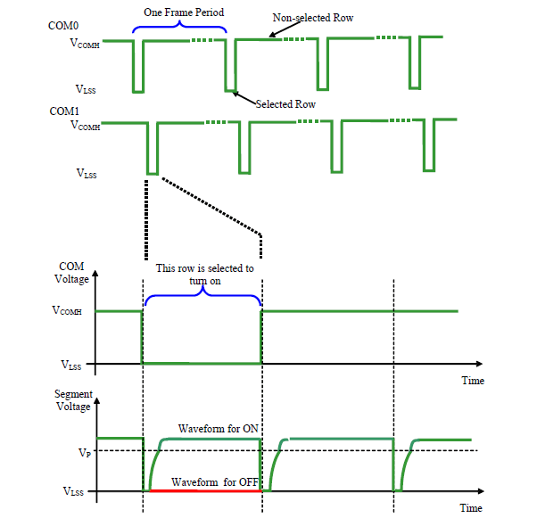
OLED segment and common driving waveforms
Varying the pulse width of the segment voltage enables the grayscale control of an OLED pixel. We can see this from the image below.

OLED pixel turn-on phases and grayscale control
Driving The Driver
Let’s write some code to control the SSD1322 driver chip. We’ll go by the sequence described in an earlier post.
Understanding the hardware interface
The SSD1322 displays data directly from GDDRAM. Our goal here is to understand how the SSD1322 represents the image data we send it. Every pixel requires 4 bits of data and can display 16 grayscale levels. As such each byte sent will contain two pixels.
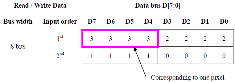
OLED data bus to RAM mapping
Each column address corresponds to four pixels as shown in the address map. In view of this we’ll have to send two bytes for each column address. We’ll configure the address increment mode to horizontal address increment.
We’ll also have to set the column start and end addresses as well as the row start and end addresses. Hence the GDDRAM address is automatically increased by one to access the next location after writing 4 pixels of data. This movement is made along our column and row start and end addresses.
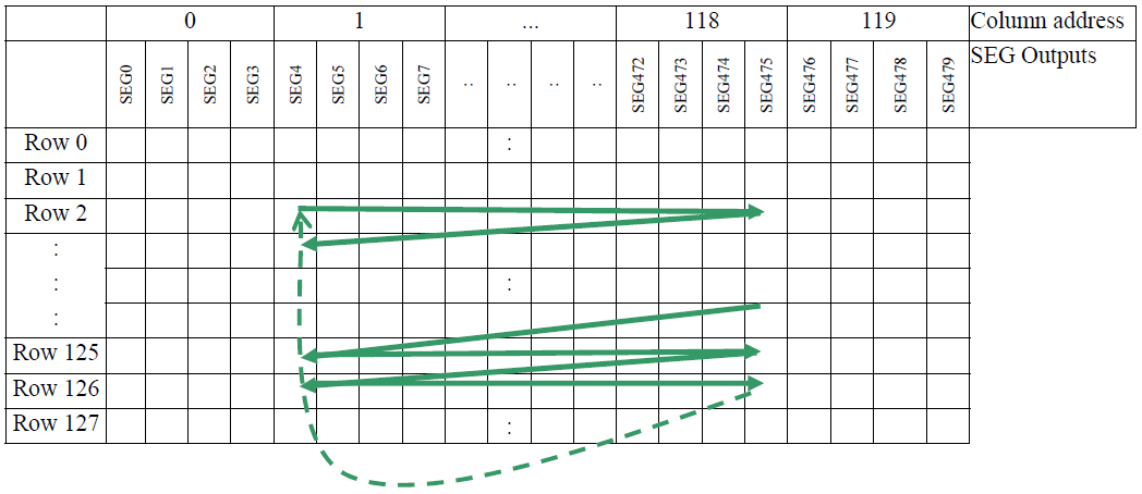
OLED RAM in horizontal address increment mode
As for a physical interface, the SSD1322 gives us a number of options including serial and parallel options. We’ll go with the 4-Wire SPI serial version for convenience and speed. By examining the datasheet we see that the SSD1322 supports SPI mode zero. Therefore we’ll configure our MCU for SPI mode zero.
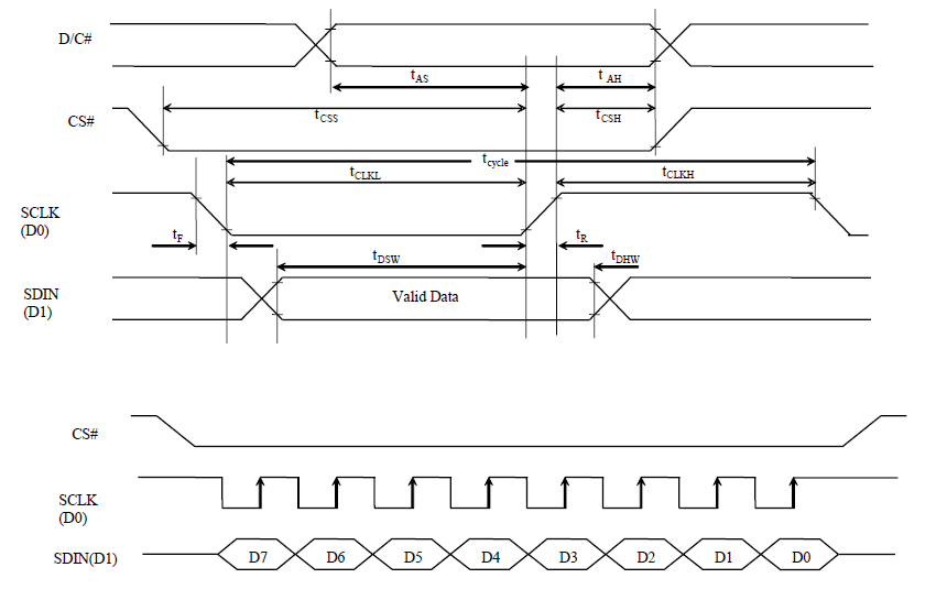
SPI timing diagram
A problem of character spacing
Once we’ve initialized our display, we can start displaying data. We’ll add functions for drawing bitmaps and outputting text.
But wait! The structure of the SSD1322 memory forces an update of 4 pixels at once. This is because each column address corresponds to 4 pixels. This will make displaying text a bit difficult because the width of a character may not align on a 4 pixel boundary. To circumvent such problems with text and images we’ll pad the resources with dummy data to ensure they align on a 4 pixel boundary. However, glyphs may have different widths of data padded which creates weird character spacing. The solution requires the use of a frame buffer.
How does a frame buffer solve this issue? The answer lies in a little more flexibility. A frame buffer provides a temporary space for drawing and manipulating data before finally outputting them to the SSD1322. We’ll provide even spacing by doing some bit shifting on the incoming character to be displayed based on the amount of padding applied to the previous character.
So before we output a character on the screen we’ll look at the padding of the previous character. A previous padding of one gives us a pixel of spacing already. Hence we’ll shift the incoming character by one pixel to the right to provide a spacing of two pixels between the previous and incoming characters. If a character is not padded we can simply manipulate the x coordinate to create spacing. We’ll take care of other scenarios by making them similar to these two base cases. Note that applying a one pixel shift to the right adds an extra pad to the incoming data.
Creating the header file
As usual our header file will contain definitions, hardware abstraction macros, data structures and function prototypes. I discussed the data structures required for the SSD1322 driver in my previous post. An excerpt from the header file shows the hardware abstraction macros and some SSD1322 commands.
// Hardware abstraction for GPIO
// Use PORTA pin 0 as chip select pin
#define CHIP_SELECT_HIGH()                      GPIOA->BSRR = GPIO_BSRR_BS_0
#define CHIP_SELECT_LOW()                       GPIOA->BSRR = GPIO_BSRR_BR_0
// Use PORTA pin 1 as data / command pin
#define DATA_COMMAND_HIGH()                     GPIOA->BSRR = GPIO_BSRR_BS_1
#define DATA_COMMAND_LOW()                      GPIOA->BSRR = GPIO_BSRR_BR_1
// Use PORTA pin 2 as chip reset pin
#define CHIP_RESET_HIGH()                       GPIOA->BSRR = GPIO_BSRR_BS_2
#define CHIP_RESET_LOW()                        GPIOA->BSRR = GPIO_BSRR_BR_2

// SSD1322 commands
#define ENABLE_GRAY_SCALE_TABLE                 0x00
#define SET_COLUMN_ADDRESS                      0x15
#define WRITE_RAM                               0x5C
#define READ_RAM                                0x5D
#define SET_ROW_ADDRESS                         0x75
#define SET_REMAP_DUAL_COM_LINE_MODE            0xA0
#define SET_DISPLAY_START_LINE                  0xA1
#define SET_DISPLAY_OFFSET                      0xA2
#define SET_DISPLAY_MODE_MASK                   0xA4
#define PARTIAL_DISPLAY_MASK                    0xA8
.
.
.
Creating the source file
Now let’s write some code. Let’s start by writing a function to talk to the SSD1322.
void ssd1322_write_data(uint8_t data)
{
    DATA_COMMAND_HIGH();
    CHIP_SELECT_LOW();
    // Write data
    HAL_SPI_Transmit(&hspi1, &data, 1, 1);
    CHIP_SELECT_HIGH();
    DATA_COMMAND_LOW();
}
We’ll initialize the display with the “ssd1322_initialize” function. This function is based on the application note provided by NewHaven Display. There is a link to the NewHaven Display app note at the end of the post.
void ssd1322_initialize(void)
{
    // Initialize DWT delay
    delay_initialize();
    .
    .
    .
    // Initialization sequence
    ssd1322_set_command_lock(COMMANDS_UNLOCK);
    ssd1322_set_display_on_off(DISPLAY_OFF);
    .
    .
    .
    ssd1322_set_display_on_off(DISPLAY_ON);
}
Let’s look at how to get interesting things unto the display. We’ll start by creating a function to display resources like text and images into a frame buffer, let’s call this function “ssd1322_put_resource_fb”. This function tries to maintain a spacing of 2 pixels while displaying text.
uint8_t ssd1322_put_resource_fb(uint8_t * fb,
                                uint8_t x,
                                uint8_t y,
                                uint8_t rows,
                                uint8_t columns,
                                uint8_t padding,
                                const uint8_t * resource_ptr)
{
    // Variables for manipulating bytes
    uint8_t temp_byte       = 0x00;
    uint8_t new_pixel_byte 	= 0x00;
    uint8_t old_pixel_byte 	= 0x00;

    // Iterators
    uint8_t i;
    uint8_t j;

    // Ignore pixel padding upon first function call
    static uint8_t previous_padding = NO_PIXEL_PADDING;
    // Temporary padding - for manipulating padding info
    uint8_t temp_padding = 0;

    // Perform character spacing with "padding compensation"
    if (x == 0 || padding == NO_PIXEL_PADDING)
    {
        previous_padding = NO_PIXEL_PADDING;
    }

    if (previous_padding == THREE_PIXEL_PADDING)
    {
        // Move the x coordinate one step back and create the appearance
        // that the previous_padding was one.
        x--;
        previous_padding = ONE_PIXEL_PADDING;
    }

    if (previous_padding == ONE_PIXEL_PADDING)
    {
        // Move to the space just after the previously displayed character
        // prior to shifting incoming pixels. This creates a character
        // spacing of 2 pixels since there is a space of 1 pixel after
        // the previous character (padding of 1).
        x++;
        // Perform a global shift of incoming pixels by one pixel to the right,
        // hence adding a pixel of spacing to the previous spacing (padding of 1)
        // This automatically increases the padding of the incoming character by one.
        for (i = 0; i < rows; i++)
        {
            for (j = 0; j < columns; j++)
            {
                new_pixel_byte = *resource_ptr++;
                temp_byte = ((new_pixel_byte >> 4) & 0x0F) | old_pixel_byte;
                fb[((y + i) * BUFFER_WIDTH) + x + j] = temp_byte;
                old_pixel_byte = (new_pixel_byte << 4) & 0xF0;
            }

            fb[((y + i) * BUFFER_WIDTH) + x + j] = old_pixel_byte;
            old_pixel_byte = 0x00;
        }

        x += columns;
        // Increase padding due to the global shift of incoming character
        // pixels to the right.
        temp_padding = padding++;
        // Padding should not be allowed to exceed 3
        if (temp_padding > 3)
        {
            // Padding immediately greater than 3 is 4
            // Move x coordinate two steps back to make it look like
            // a padding of 0 was added to current character
            x -= 2;
            temp_padding = ZERO_PIXEL_PADDING;
        }
    }

    if (previous_padding == TWO_PIXEL_PADDING)
    {
        // Display character right after the previous character since there is
        // a spacing of 2 pixels after the previous character (padding of 2)
        x++;
        previous_padding = NO_PIXEL_PADDING;
    }

    if (previous_padding == ZERO_PIXEL_PADDING)
    {
        // Leave a space of 1 byte (2 pixels) after the previously displayed
        // character since there is no space after the character (padding of 0)
        x += 2;
        previous_padding = NO_PIXEL_PADDING;
    }

    if (previous_padding == NO_PIXEL_PADDING)
    {
        // Display incoming pixels at the current x coordinate
        for (i = 0; i < rows; i++)
        {
            for (j = 0; j < columns; j++)
            {
                fb[((y + i) * BUFFER_WIDTH) + x + j] = *resource_ptr++;
            }
        }

        x += columns - 1;
        temp_padding = padding;
    }

    // Update previous padding
    previous_padding = temp_padding;

    // Return the current x coordinate of the frame buffer
    return x;
}
From here we can make various calls to “ssd13322_put_resource_fb” to display text and images. Displaying a bitmap is straightforward, we just have to call “ssd1322_put_resource_fb” and pass the bitmap info. Bitmaps don’t require any spacing unlike text and hence any padded data is assumed as part of the bitmap.
uint8_t ssd1322_put_bitmap_fb(uint8_t * fb,
                              uint8_t x,
                              uint8_t y,
                              const bitmap_t * bmp)
{
    // Display bitmap
    x = ssd1322_put_resource_fb(fb, x, y, bmp->height, (bmp->width * 2), \
                                NO_PIXEL_PADDING, bmp->address);

    // Return the current x coordinate of the frame buffer
    return x;
}
Displaying text is also fairly straightforward from here. All we have to do is unpack the glyph metadata from the font table and make a call to “ssd1322_put_resource_fb”.
uint8_t ssd1322_put_char_fb(uint8_t * fb, uint8_t x, uint8_t y, const char c)
{
    // Fetch glyph metadata
    uint16_t glyph_offset  = g_active_font->font_table[c - ' '].glyph_location;
    uint8_t  columns       = g_active_font->font_table[c - ' '].glyph_width;
    uint8_t  rows          = g_active_font->font_table[c - ' '].glyph_height;
    uint8_t  baseline      = g_active_font->font_table[c - ' '].glyph_baseline;
    uint8_t  padding       = g_active_font->font_table[c - ' '].dummy_added;

    // Get location of glyph in font
    const uint8_t * glyph_address = g_active_font->address + glyph_offset;
    // Calculate correct glyph baseline
    y += baseline;
    // Display glyph
    x = ssd1322_put_resource_fb(fb, x, y, rows, (columns * 2), \
                                padding, glyph_address);

    // Return the current x coordinate of the frame buffer
    return x;
}
Now that we can display characters, handling strings should be a breeze. We’ll create a function to display text based on our character displaying function.
uint8_t ssd1322_put_string_fb(uint8_t * fb,
                              uint8_t x,
                              uint8_t y,
                              const char * string)
{
    while (*string)
    {
        x = ssd1322_put_char_fb(fb, x, y, *string++);
    }

    // Return the current x coordinate of the frame buffer
    return x;
}
So far we can put text and images into a frame buffer but we need a function to send the data to the SSD1322. Finally let’s create the “ssd1322_display_fb” function to dump the contents of the frame buffer to the display.
void ssd1322_display_fb(uint8_t * fb)
{
    uint8_t i;
    uint8_t j;

    ssd1322_set_address(0, 0);

    for (i = 0; i < BUFFER_HEIGHT; i++)
    {
        for (j = 0; j < BUFFER_WIDTH; j++)
        {
            ssd1322_write_data(fb[(i * BUFFER_WIDTH) + j]);
        }
    }
}
Displaying Text And Images
To display text and images we’ll first have to generate C code for the text and images we want to display. I’ve put together a python script for converting resource files into source code and a tutorial to go along with it. After generating code for the text and images, we’ll have to add the resources to our microcontroller project. We can create a source code folder for our driver code and resources. We just have to remember to update the include paths when building the project.
Let’s go ahead and include the header files of the resources in our “main.c” file.
#include "bitmaps.h"
#include "PTM55FT.h"
#include "Lato_Regular.h"
#include "IBMPlexMono_Regular.h"
We’ll create a frame buffer by allocating 8192 bytes of memory, we need this much because of the display size (256 x 64 x 4 bits).
uint8_t *frame_buffer = (uint8_t *) calloc(8192, sizeof(uint8_t));
Now let’s initialize the SSD1322 driver and delay routines.
delay_initialize();
ssd1322_initialize();
Finally we’ll go ahead and make calls to SSD1322 driver functions to display images and text.
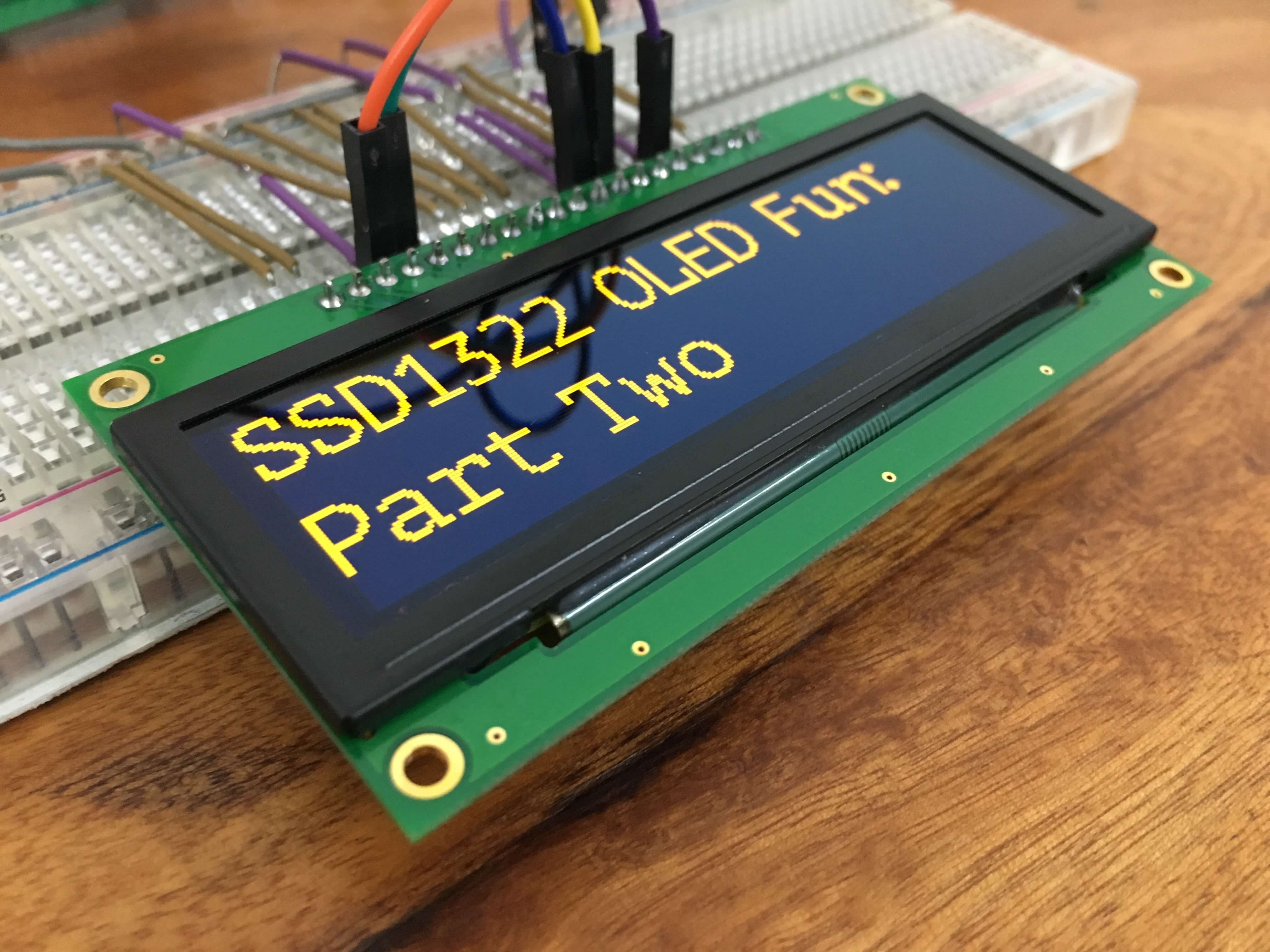
// Display images on screen
ssd1322_fill_fb(frame_buffer, 0x00);
ssd1322_put_bitmap_fb(frame_buffer, 0,  0, (const bitmap_t *) &einstein_0);
ssd1322_put_bitmap_fb(frame_buffer, 33, 0, (const bitmap_t *) &einstein_1);
ssd1322_put_bitmap_fb(frame_buffer, 60, 0, (const bitmap_t *) &einstein_2);
ssd1322_put_bitmap_fb(frame_buffer, 91, 0, (const bitmap_t *) &einstein_3);
ssd1322_display_fb(frame_buffer);
delay_ms(20000);

// Display text on screen
ssd1322_set_font((const font_t *) &PTM55FT);
ssd1322_fill_fb(frame_buffer, 0x00);
ssd1322_put_string_fb(frame_buffer, 0, 0,  "SSD1322 OLED Fun:");
ssd1322_put_string_fb(frame_buffer, 0, 32, "Part Two");
ssd1322_display_fb(frame_buffer);
delay_ms(20000);
The image below shows how the bitmaps displayed appear on screen.
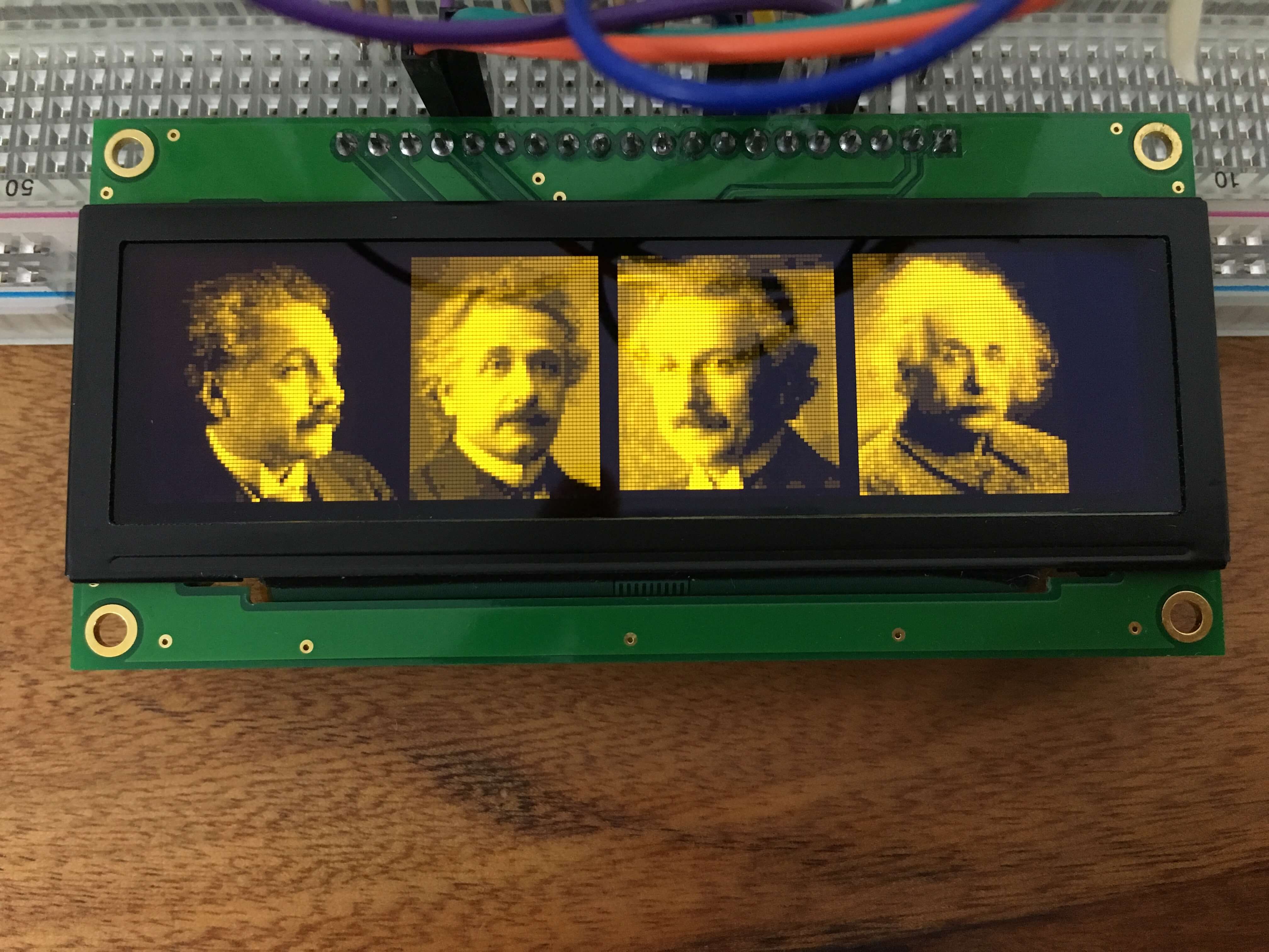
Displaying bitmaps on the SSD1322 OLED display
The banner image of this post shows how displayed text looks like. All the code for this project is available on Github.
References
This work is based on the example code provided by NewHaven Display. You can check it out using the link below: https://www.newhavendisplay.com/appnotes/excode/txt/OLED/OLED_25664.txt