
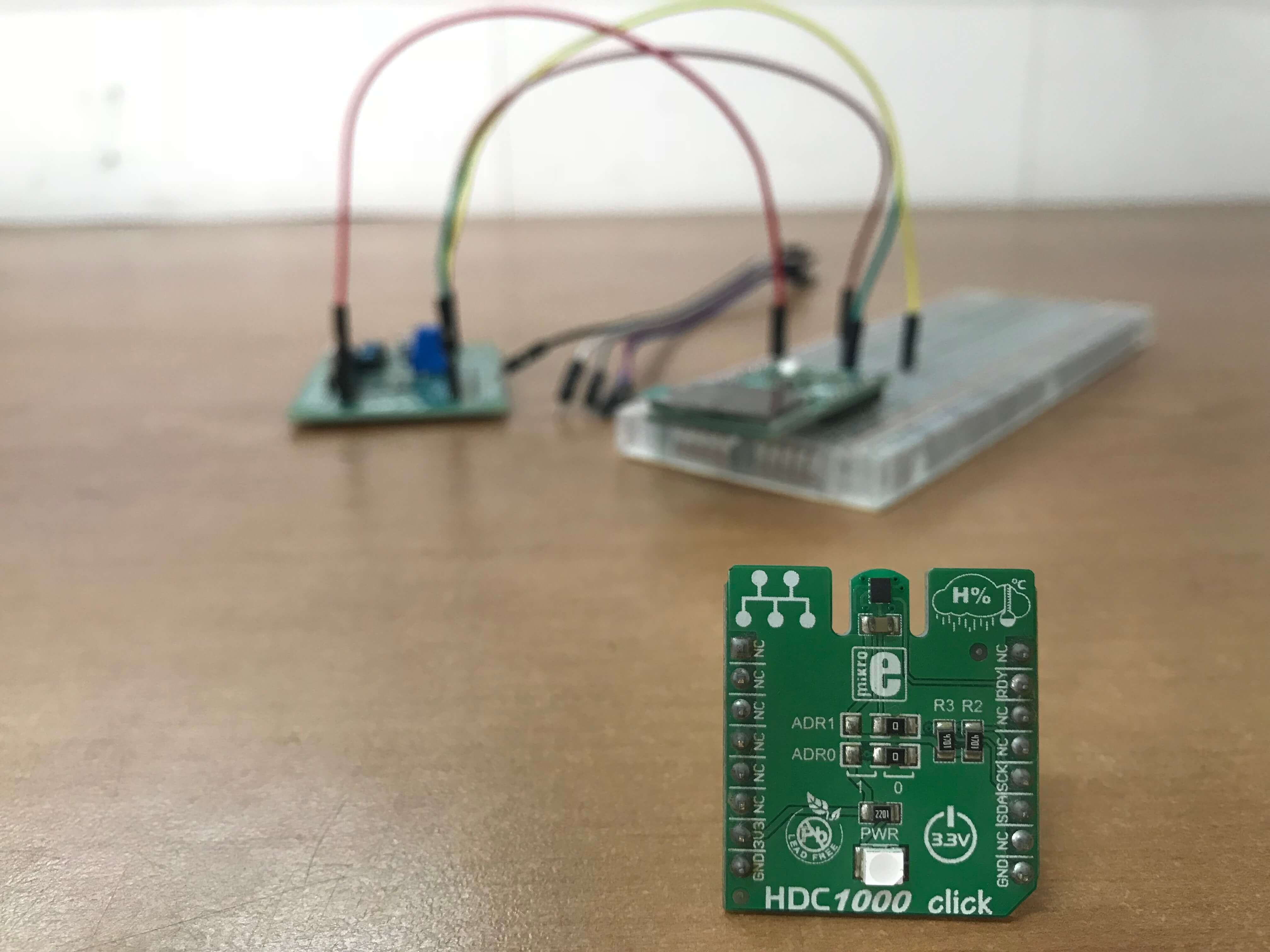
 Embedded drivers are the glue between software and hardware, and are a very important part of embedded systems. In other words embedded drivers enable us to easily talk to chips using interfaces like TWI (Two Wire Interface) because unfortunately chips don’t speak English – pun intended. Being able to write simple embedded drivers is a good skill to have although platforms with good libraries like Arduino exist. You don’t want to be stuck on a project because you can’t find a library for a critical chip in your design. I’ll use the HDC1000 chip from Texas Instruments as an example for writing embedded drivers. Let’s dive in.
Reading The Datasheet
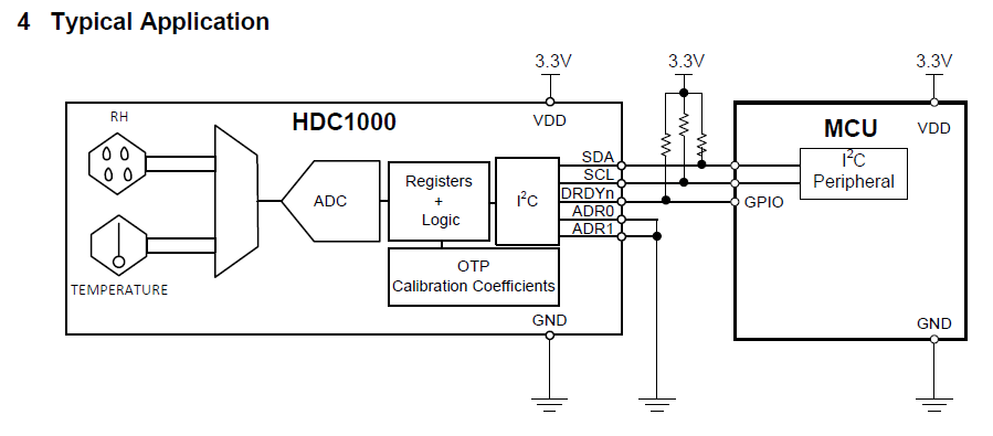
Datasheets contain all the technical information you need to write your embedded driver. Reading datasheets is a very important engineering skill. Datasheets are organised in sections which describe various aspects of the chip. The first page of a datasheet usually contains the features, applications and a basic description of the chip. From this page we get to know the chip and its major applications. Now we know that the HDC1000 is a temperature and humidity sensor with an I2C interface. We also get a schematic of a typical application which is very useful.
Application Circuit
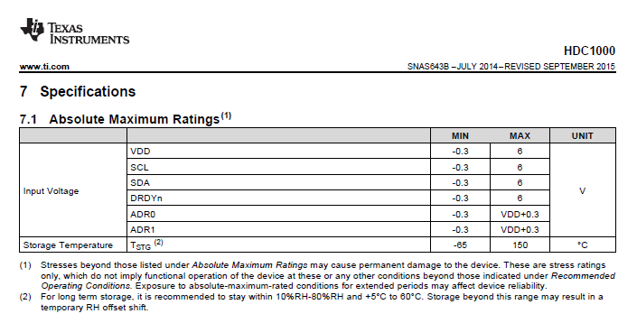
Section 6 of the datasheet contains the pin information of the HDC1000, this tells us the function of each pin and its location on the chip. This info is key when we build the physical circuit. Section 7 of the HDC1000 datasheet describes the electrical specifications of the chip. In section 7.1 we find the absolute maximum ratings of the chip. It is very important that we don’t exceed the parameters listed in the absolute maximum ratings to avoid damaging our chip. Electrical characteristics, I2C interface characteristics, a timing diagram and characteristic graphs are also found in section 7 of the HDC1000 datasheet.
Absolute Maximum Ratings
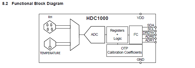
We can find a detailed description of the workings of the chip along with a block diagram in section 8 of the datasheet. From the functional block diagram we can see that there are two sensing elements, one for relative humidity and one for temperature. The sensors are multiplexed into an ADC which is controlled by registers and logic. The registers and logic are connected to calibration coefficients which are one time programmable. And finally there is an I2C block which enables us to interface/talk to this chip with pretty much any microcontroller.
Functional Block Diagram
Using The Datasheet
Here comes the fun part. Let’s get to know the individual registers which control the chip and how to properly configure them. At this point I usually pull out a piece of paper and take some notes to simplify programming. There are 8 registers inside the HDC1000, but we need to bother about 3 for now. The configuration register is for setting up the chip. The configuration register controls the order of readout and resolution of our temperature and humidity measurements. The temperature and humidity registers contain our measured values. In summary this is what we need to do in software:
- Configure the chip for readout by setting the acquisition mode and selecting the measurement resolution.
- Trigger a measurement.
- Wait for the measurement to complete.
- Read the output data.
Step 1 has to be done at least once, but steps 2-4 must be repeated for every measurement. At this point we can start writing the driver using our datasheet as a reference.
Writing The Header File
We need a header file for definitions and function prototypes, for this example we will create a file called “hdc1000.h”. So now we simply need a bunch of functions to do the following:
- Abstract I2C functionality; reading and writing to the chip.
- Provide functions for HDC1000 register access.
- Provide functions for acquiring temperature and humidity data.
We will define the registers of the HDC1000 so we can use them in our functions.
// HDC1000 I2C and register addresses
#define HDC1000_ADDRESS         0x40
#define TEMPERATURE_REGISTER    0x00
#define HUMIDITY_REGISTER       0X01
#define CONFIG_REGISTER         0X02
#define SERIAL_ID_1             0xFB
#define SERIAL_ID_2             0xFC
#define SERIAL_ID_3             0xFD
#define MANUFACTURER_ID         0xFE
#define DEVICE_ID               0xFF
We will also define masks for setting bits in the configuration register
// Useful for setting and clearing bits of the configuration register
#define HEATER_ON              0x2000
#define HEATER_OFF             0x0000
#define MODE_TEMP_OR_HUMID     0x0000
#define MODE_TEMP_AND_HUMID    0x1000
#define BATTERY_STATUS_MASK    0x0800
#define TRES_11                0x0400
#define TRES_14                0x0000
#define HRES_8                 0x0200
#define HRES_11                0x0100
#define HRES_14                0x0000
Lastly we write our function prototypes
void hdc1000_read(uint8_t length, uint8_t * data_ptr);
.
.
.
uint16_t * hdc1000_get_everything(void);
Writing The Source File
Let’s create a file called “hdc1000.c” to implement our functions in. Firstly, let’s include the necessary header files. The first line gives us access to microchip’s I2C driver for 8 bit PICs. The second line provides us with function prototypes for our code.
#include "mcc_generated_files/mcc.h"
#include "hdc1000.h"
Instead of using the I2C functions directly let’s create a wrapper function to abstract the native I2C functions of the MCU. This is a nice and easy way of enhancing portability. Below is a function for reading data from the HDC1000. The code for writing data to the HDC1000 is very similar to this.
void hdc1000_read(uint8_t length, uint8_t* data_ptr)
{
    // Set status to -1 in order for loop to run at least once
    I2C1_MESSAGE_STATUS status = -1;
    uint8_t time_out = 0;

    while (status != I2C1_MESSAGE_FAIL && status != I2C1_MESSAGE_COMPLETE \
           && time_out < HDC1000_I2C_TRY_MAX)
    {
        I2C1_MasterRead(data_ptr, length, HDC1000_ADDRESS, &status);
        // Wait for I2C transaction to complete
        while (status == I2C1_MESSAGE_PENDING);
        // Try again if something goes wrong
        time_out++;
    }
}
Next we need functions to access registers in the HDC1000 sensor. We need to let the chip know which register we want to access. We do this by writing the address of the register we want to access before we perform any read or write transaction. The code for writing data to a register is shown below. It is similar to the code for reading data from a register. You’re probably wondering why there’s a delay before reading data from the chip. Doing this allows us to simplify the functions for reading temperature and humidity by just calling this one function. We will be reading temperature and humidity data more often than other registers. Hence there will be a small performance penalty of 8 milliseconds when reading data from other registers!
uint16_t hdc1000_get_reg(uint8_t address)
{
    uint8_t data[2] = {0, 0};
    data[0] = address;
    // Send address of register
    hdc1000_write(1, &data[0]);
    // Wait for conversion to complete
    __delay_ms(8);
    // Read data from specified address
    hdc1000_read(2, &data[0]);
    return (data[0] << 8) + data[1];
}
Lastly, let’s look at the functions for reading the temperature and humidity. All we have to do is call the “hdc1000_get_reg” function and pass the address of the temperature or humidity register. You can implement the functions below as macros to improve performance.
uint16_t hdc1000_get_temperature(void)
{
    return hdc1000_get_reg(TEMPERATURE_REGISTER);
}

uint16_t hdc1000_get_humidity(void)
{
    return hdc1000_get_reg(HUMIDITY_REGISTER);
}
Using The Driver
It’s time to enjoy our efforts. Let’s add our source and header files to a project in order to use the driver. We have to include the header file in our main file to access the functions provided. To configure/initialize the chip we can use the code below.
// Set acquisition mode to enable either a temperature or humidity conversion.
// This is a precondition for calling hdc1000_get_temperature() and
// hdc1000_get_humidity() functions.
hdc1000_set_reg(CONFIG_REGISTER, MODE_TEMP_OR_HUMID | TRES_14 | HRES_14);
After initialization we can trigger measurements at will. All measurements are in a raw format. The datasheet provides us with formulas for calculating the temperature and humidity using the raw data.
temperature_raw = hdc1000_get_temperature();
humidity_raw = hdc1000_get_humidity();

// Convert temperature into degrees Celsius
temperature = ((temperature_raw / 65536.0) * 165.0) - 40.0;
// Convert relative humidity into a percentage
humidity = (humidity_raw / 65536.0) * 100.0;
Here is a serial output of our demo viewed with pyserial in a python script.
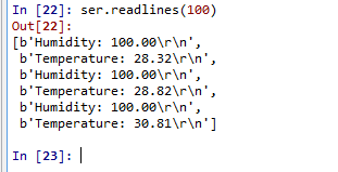
Serial Output
Porting To Other Platforms
I have personally ported this driver to the MSP430 with minimal modifications. The major modification needed is to replace the code in the “hdc1000_read” and “hdc1000_write” functions with the I2C functions of the platform you’re porting to.
Summary
You can find the source code along with documentation here. Looking to add an LCD display to the demo? Check out my earlier post.
Kwaku Addo
Great work, Adom. Keep the posts coming.
Kwabena
Thank you Kwaku
Yaw Obeng
Very informative. Glad I found this.