
Whether you’re designing a thermometer, a radio or some sort of embedded gadget, an LCD is a great way to show information to and interact with the user. The HD44780 is a popular dot matrix LCD controller from Hitachi. In this post I’ll talk about how to communicate with LCD displays which use the HD44780 chip.
Hardware Interface
There are a few things we need to understand about our LCD controller before interfacing with it. The HD44780 LCD driver is a complex circuit comprising a number of different blocks, we can abstract a lot of this information away and think of it at a higher level. We can think of the HD44780 as a system that takes data we want to display and shows them on an LCD. The HD44780 employs a parallel interface and supports data writes in 4-bit or 8-bit mode. Using the chip in 4-bit mode allows the user to save 4 I/O pins on the microcontroller – we’ll be using the 4-bit mode in this post. The pins of the HD44780 that we’ll need to care about are; RS (Register Select), E (Enable), R/W(Read/Write), DB0-DB7(Data lines).
The image below shows a typical LCD circuit, the LCD comes as a module with the HD44780 chip on board. From the schematic you can see that the R/W pin is grounded, this is because we can ignore the use of this feature by not reading data from the LCD. Pins D0, D1, D2 and D3 are also grounded in the schematic, this is because we are using the LCD in 4 bit mode and we only need the last four data pins to talk to the chip. In the circuit below I added a display brightness control feature using PWM, you can simply connect the LED- pin of the LCD module to ground if you don’t need this feature.
Software Interface
There are two internal 8-bit registers; a data register and an instruction register. The RS pin allows us to select which register to access when we are sending data to the chip. The timing diagram in the datasheet shows us how to send electrical signals(Data) to the HD44780, this will inform how we code the “LCD_write” function. The Enable pin is what tells the HD44780 that there is data on the DB0-DB7 lines. This data can be 4 or 8 bits long. A pulse on the Enable pin represents a valid piece of data as shown in the timing diagram below.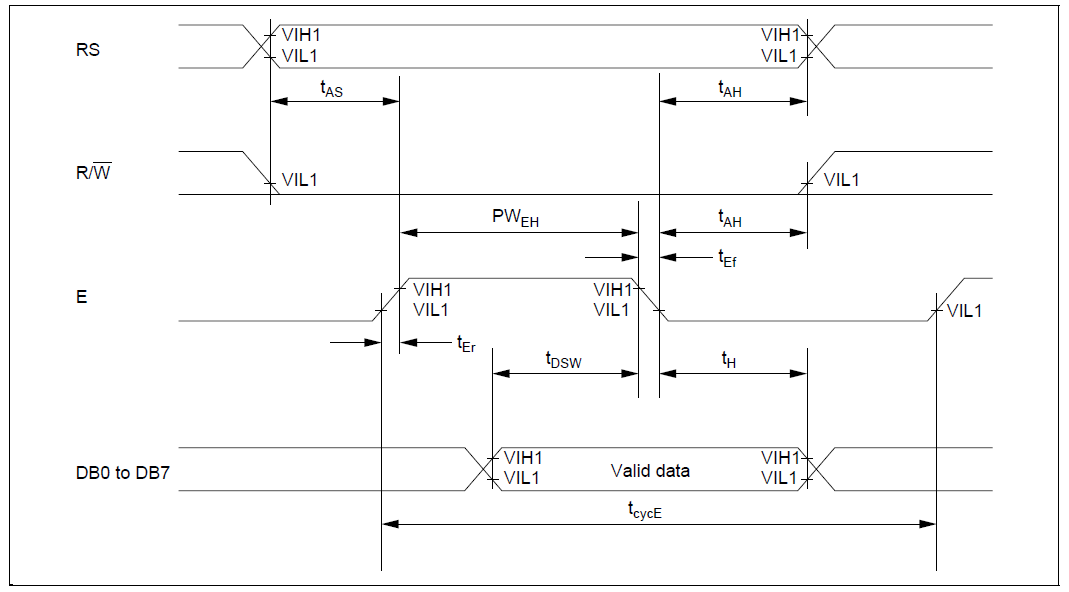
We can poll the status of the LCD to determine whether it is ready to accept new data or not, instead we will just insert delays in our code adequate enough for the LCD to process the data we feed it, hence we can ground the R/W pin. We have to send two nibbles of data in 4-bit mode since the registers are 8-bit wide. All we have to do now is write some code.
Putting it all together
Now let’s consider the functions needed to bring our LCD to life. We’ll need a function to send data (data/instructions) to the HD44780. Secondly, we’ll need a function to initialize the chip and put it in 4-bit mode. Thirdly we’ll need functions to send commands and 8-bit data to the chip. And lastly we’ll need functions to display characters and strings on the LCD.
To send data to the HD44780 we’ll compose both nibbles from the same byte. The “LCD_Write” function displays either the upper or lower nibble from a byte.
static void LCD_Write(const char nibble, uint8_t register_select)
{
    (nibble & 0x08 || nibble & 0x80) ? LCD_D7 = 1 : LCD_D7 = 0;
    (nibble & 0x04 || nibble & 0x40) ? LCD_D6 = 1 : LCD_D6 = 0;
    (nibble & 0x02 || nibble & 0x20) ? LCD_D5 = 1 : LCD_D5 = 0;
    (nibble & 0x01 || nibble & 0x10) ? LCD_D4 = 1 : LCD_D4 = 0;

    // Register Selection
    LCD_RS = register_select;

    // Clock data into LCD
    __delay_us(1);
    LCD_EN = 1;
    __delay_us(1);
    LCD_EN = 0;
}
Initializing the LCD is done by sending specific commands to the HD44780. These commands control how data is displayed on the LCD and whether data is sent in 4-bit or 8-bit mode.
    // Start operation in 4 bit mode
    LCD_Write(0x02, CMD);
    __delay_ms(1);
    // Number of display lines and character font
    LCD_Write(0x02, CMD);
    LCD_Write(0x08, CMD);
    __delay_ms(1);
         .
         .
         .
    // Set Entry mode
    LCD_Write(0x00, CMD);
    LCD_Write(0x06, CMD);
    __delay_ms(1);
One disadvantage of using 4-bit mode is that we have to send the same data sort of twice. We send the upper and lower nibbles of the same 8 bit data separately.
void LCD_PutChar_Cp(const char c)
{
    // Send upper nibble first
    LCD_Write((c & 0xF0), DATA);
    // Send lower nibble next
    LCD_Write((c & 0x0F), DATA);
    __delay_us(100);
}
Building upon the “LCD_PutChar_Cp” function we can just add a while condition to display strings.
void LCD_PutString_Cp(const char *s)
{
    while (*s)
    {
        LCD_PutChar_Cp(*s++);
    }
}
Using the LCD
You’re probably not going to use the same hardware connections I typically use so you have to edit the header file in order to use a different hardware connection. The code below shows a sample hardware configuration.
// Hardware abstraction
#define LCD_RS  LATB4
#define LCD_EN  LATB5
#define LCD_D4  LATB0
#define LCD_D5  LATB1 #define LCD_D6  LATB2
#define LCD_D7  LATB3
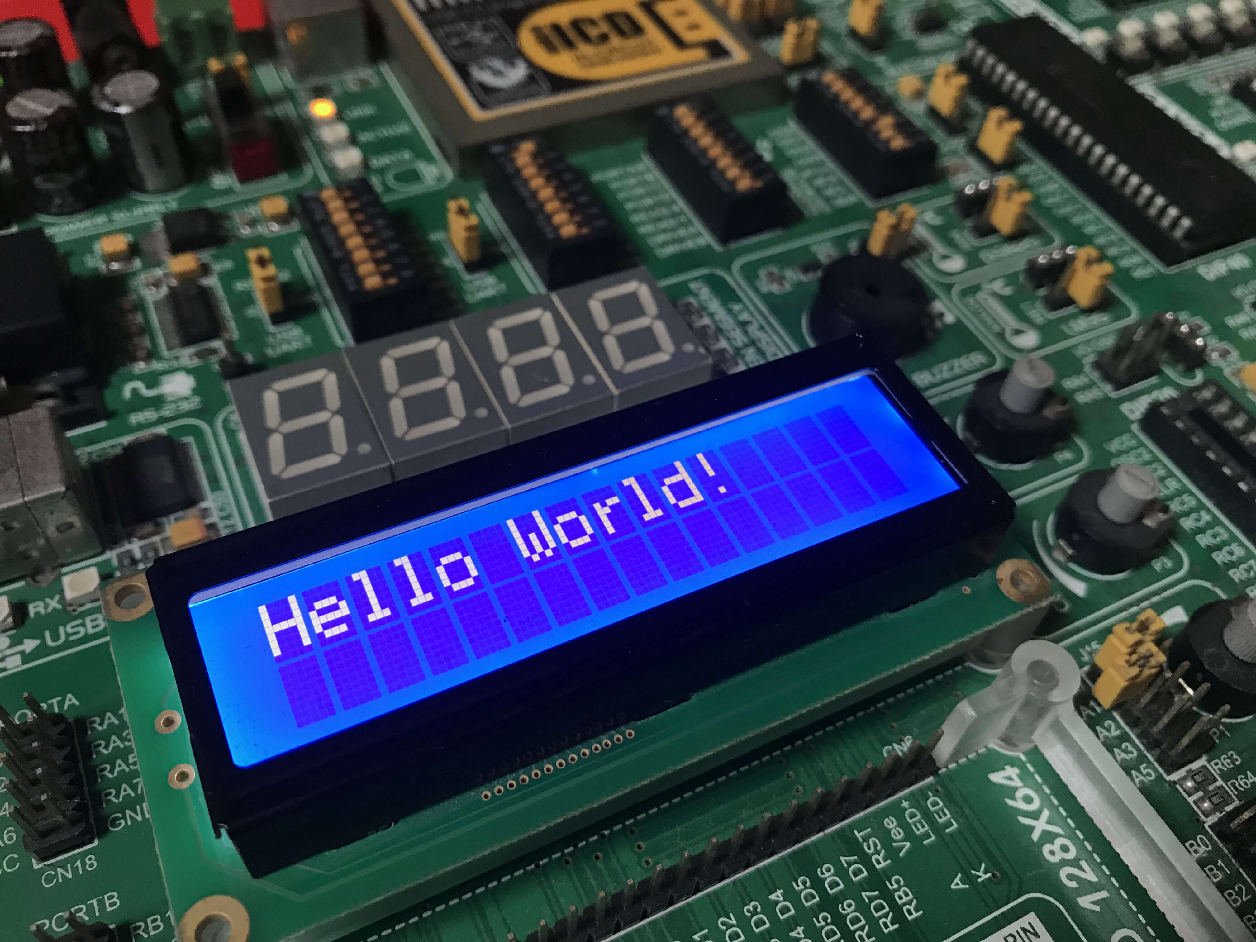
Here is a simple LCD hello world project.
// Initialize LCD display
LCD_Init();
LCD_PutCmd(_LCD_CLEAR);
LCD_PutCmd(_LCD_CURSOR_OFF);
// Display some text on the first row
LCD_PutString(1, 1, "Hello World!");
Documentation
The code for this project is available on Github. Porting the code to other platforms is easy, you just have to replace the hardware dependent portions of the code with equivalent code for your target system, the rest is plain C.